
MEDIUM-VOLTAGE DISTRIBUTION / PROTECTION
MV
Switchgear.
Switch with purpose.
Protect with a plan.
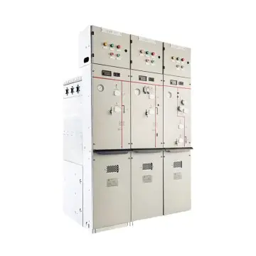
Medium-voltage switchgear configured around your single-line diagram, operating duty and protection scheme. Review the insulation arrangement, circuit functions and site interfaces together.
Project-specific selection. Clear technical documentation.
01 / THE RIGHT FIT
Build the lineup
around the network.
Medium-voltage switchgear controls and protects circuits within a distribution system. Equipment selection starts with the network voltage, load current, fault duty and required operating functions.
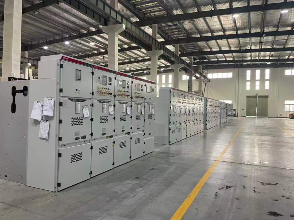
VoltGrid reviews the panel schedule, insulation arrangement and protection interfaces against the project specification. Cable access, service space and extension requirements are part of the same review.
Specify every circuit function
Identify incomers, feeders, bus couplers, metering and other required functions before finalizing the lineup.
Coordinate primary and secondary systems
Bring protection relays, instrument transformers, controls, interlocks and auxiliary supplies into the equipment scope.
02 / CONFIGURATION OPTIONS
Choose the arrangement.
Define the panel functions.
Insulation and access requirements influence the design. Availability and suitability of each arrangement are confirmed during technical review.
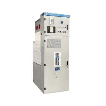
Air-insulated switchgear
Review air-insulated arrangements against the room layout, fault duty and service requirements.
- Define fixed or withdrawable requirements
- Review isolation, interlocks and maintenance access
- Confirm dimensions and future extension needs
Gas-insulated switchgear
Review gas-insulated arrangements where the project calls for this insulation approach.
- Specify voltage, current and switching functions
- Agree insulating medium and environmental requirements
- Review service procedures, monitoring and interfaces
- Incoming supply
- Switch & protect
- Outgoing feeders
Feeder & ring arrangements
Configure circuit functions around a radial or ring distribution scheme.
- Define incoming, outgoing and transformer circuits
- Specify switching, earthing and protection functions
- Coordinate remote indication and control if required
RING NETWORK / REFERENCE PHOTOS
A closer look at ring-main arrangements.
Four-bay equipment shown for visual reference. Feeder functions, switching, protection and cable interfaces are defined for each project.
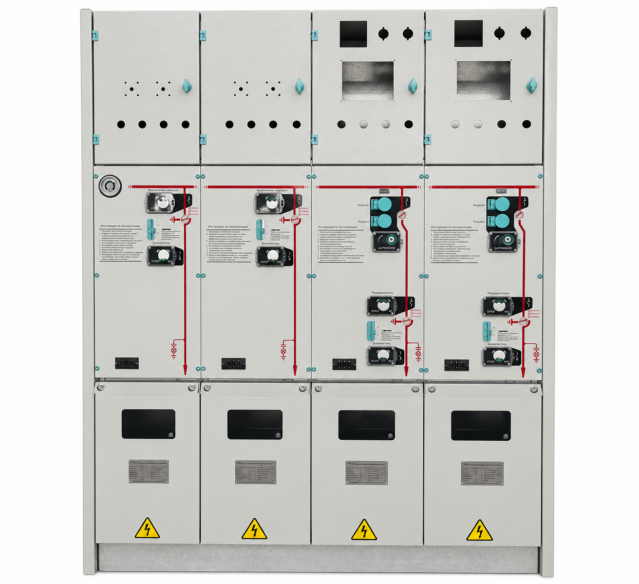
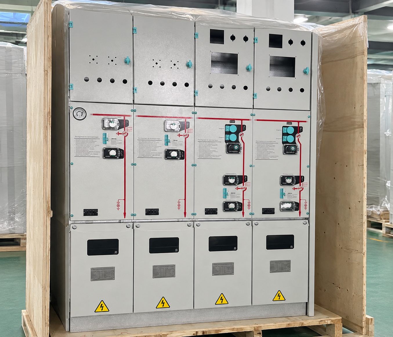
Visual references edited from supplied photos. Final equipment details are confirmed in approved drawings.
AIS / GIS describes the insulation approach. Fixed / withdrawable and radial / ring describe other aspects of the design and should be specified separately.
Protection and control
belong in the first brief.
These inputs affect the panel design, wiring and commissioning requirements.
Fault duty & protection
Provide the prospective short-circuit duty, duration and required protection functions.
Metering & signals
Define CT / VT requirements, relay interfaces, indication and communications.
Access & interlocks
Specify operating access, earthing, interlocking and any internal arc classification requirements.
03 / TECHNICAL SELECTION
From single-line
to panel schedule.
Send the network diagram and panel schedule with the electrical and site requirements. Confirm the applicable ratings and verified performance in the final proposal.
Enquiry checklistPDF · Project specification worksheet| Selection parameter | What to confirm |
|---|---|
| System voltage | Nominal voltage, highest equipment voltage and insulation level |
| Current & frequency | Busbar and feeder currents, system frequency and loading conditions |
| Short-circuit duty | Short-time withstand, peak duty, duration and interrupting requirements |
| Circuit schedule | Incomers, feeders, coupling, metering and reserve / extension positions |
| Insulation & arrangement | AIS / GIS, specified insulating medium and fixed / withdrawable needs |
| Protection & metering | Relay functions, CT / VT data, meters and auxiliary supply |
| Control & interlocking | Local / remote control, communications, signals and operating interlocks |
| Installation | Indoor / outdoor, cable entry, access clearances and environmental conditions |
| Tests & evidence | Applicable standards, internal arc requirements if specified, and test documentation |
Specific ratings, availability and supporting evidence are confirmed for the proposed equipment.
04 / APPLICATIONS
Built around
the way you use power.
Bring the application into the specification.
It shapes the equipment and the interfaces.
Distribution substations
Switching and protection of utility distribution circuits.
Focus: Fault duty & operating functionsIndustrial facilities
Control of plant feeders and large electrical loads.
Focus: Protection coordination & service accessRenewable energy sites
Switching interfaces within collection and connection systems.
Focus: Network arrangement & remote signalsInfrastructure & buildings
Medium-voltage supplies to campuses and major facilities.
Focus: Room layout & continuity requirements05 / PROJECT SUPPORT
From your requirements
to a defined supply.
Agree the equipment scope, supporting documents and project interfaces at each stage.
- 01
Review the single-line
Identify circuit functions, ratings and operating requirements.
- 02
Develop the lineup
Coordinate insulation, panel arrangement and cable interfaces.
- 03
Confirm secondary systems
Review relays, metering, interlocks and control schematics.
- 04
Agree verification
Define drawings, tests, inspection and commissioning information.
06 / COMMON QUESTIONS
Before you
specify.
Practical questions about mv switchgear selection and project requirements.
Ask a technical questionHow do I choose between AIS and GIS?
Consider the electrical duty, available space, environment, service strategy and project requirements. The insulation medium and environmental obligations must also be specified. The right choice is based on the complete installation.
Are fixed and withdrawable designs the same as AIS and GIS?
No. Fixed or withdrawable describes an equipment access or removal arrangement, while AIS or GIS describes the insulation approach. State both requirements where relevant to the project.
What information is needed for a protection package?
Provide the single-line diagram, fault-level information, protection philosophy, CT / VT requirements, auxiliary supplies and any relay or communication preferences. Settings and coordination should be established by the responsible protection engineer.
Is internal arc classification automatic?
No. Where required, specify the classification, accessibility, test current and duration, and verify supporting evidence for the offered design. Installation conditions and pressure-relief arrangements also need review.
Can a lineup be extended later?
Extension needs should be identified at the initial design stage. Busbar interfaces, panel arrangement, room space and outage requirements must be suitable for the planned extension.
LET’S DEFINE YOUR NEXT PROJECT
Your requirements.
Our starting point.
Tell us what you are planning. Include “MV Switchgear” in your message and share the information you have available.
- Single-line diagram, panel schedule and voltage class
- Bus / feeder currents, short-circuit duty and protection requirements
- Installation layout, control interfaces and applicable standards
Request a project review
Start the conversation with our team.